Start With the Problem
The simplest means of treating machine and board repairs is to start with the obvious problem and then try to isolate the cause. Treat each potential output problem individually, and trace it from the exterior of the machine to one of the processor boards, through the point of opto-isolation. Opto-isolation is a defense against static electricity, noise, or any unwanted electrical feedback. The technician should verify each problem in the output test. The technician can then reference each output in question in this manual. When using the diagram provided with each output problem, the following items should be kept in mind:
- Each output can be activated by a signal through the wiring and connectors from the motherboard.
- The motherboard connects the signal from the processor board (processor
- board connects to the motherboard at J/P 1 and J/P 2).
- The processor board typically has a driver (e.g. triac) that connects to an output pin on the parallel side of the shift register.
Outputs Section of the Processor Board
The outputs section contains four 8-bit output latches (U33, U35, U37, and U39). Each output latch requires a steady low on its pin 1 and a clock pulse on-pin 11. With these two conditions satisfied, the output latches can update the outputs from the data-bus. The output side of the output latches is a buffer and current limiting resistor for each output bit and then opto-isolation. From the point of opto-isolation on, is the driver area (the area most susceptible to damage). The majority of drivers are triacs (AC switches). Two output drivers are NPN transistors and digital switches (jackpot out and door open).
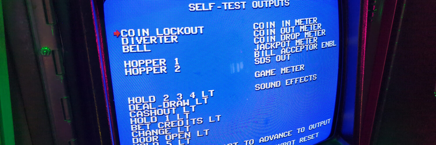
Outputs Test
The message SELF-TEST OUTPUTS appears at the top of the video screen. Below it are the names of the available outputs. An arrow-shaped cursor, located to the immediate left of the output names, indicates which output is under test. Consult the on-screen instructions and press the indicated switch on the player panel to move the cursor from one output to the next. Turn the reset key to activate most outputs. Most tests illuminate one or more player panel switches to advance the cursor. The lockout test activates the LED indicator on the coin comparitor and the sound effects test produces a tone from the speaker. To activate the bill acceptor, insert a dollar bill.


Add comment